Krystals 4.0
See also: Krystals 4.0 is a program which provides an environment in which to create krystals. It builds on the code and ideas in my previous (unpublished) krystals software. It is the first major program I wrote with Microsoft's Visual C# (2006).The best way to learn any new language and/or programming environment is to solve a concrete problem, and this was the problem I chose. The result is a program which works (and which I use), but which has a few er... idiosyncrasies in its code. Instead of tinkering with these, it would be better to reprogram the whole thing again from scratch — but I can’t imagine getting round to that for some time...
The code library containing the more abstract classes (krystal, strand etc.) is however now part of Moritz, and is continuing to be developed and maintained. The most recent use of this library is in the development of Moritz’ shaped expansion and permutation nodes. Krystals 4.0 does not do permutation, even though pk was part of Krystals 3.0 when I published my first website in 1999
(see footnote 1 of A short introduction to krystals). For a detailed descrption of the concepts involved, see Krystal Permutation.
Contents:
XML Schema
The XML file formats and naming conventions for Krystals 4.0 are defined in the schema file krystals.xsd. These definitions are also used by Moritz.Definitions
Here are some more definitions, building on those in A short introduction to krystals.- A krystal operator or simply operator
is an obect (such as an expansion field or modulation array etc.) which can use one or more
krystals to create a new one.
-
An expander is a field containing input and output points, as described in the short
introduction. I sometimes use the term ‘expansion field’, but this is
a bit clumsy.
An expander is an operator. - A gamete is a set of input or output points in an expander. An expander has an input gamete and an output gamete.
- A planet is an input point or an output point which moves (wanders) while an expansion is being created.
File Names
The names of krystals and their operators are allocated automatically. Here is what they mean/contain:A constant krystal file name has the form:
ck0(<value>).krys
where:
<value> is the value of the krystal.
For example: ck0(4).krys, ck0(17).krys, ck0(56).krys
etc.A line krystal file name has the form:
lk1(<domain>)-<index>.krys
where:
<domain> is the maximum value in the krystal.
<index> a number which differentiates krystals which would otherwise have the same name.
For example: lk1(7)-12.krys, lk1(12)-2.krys, lk1(100)-1.krys<index> a number which differentiates krystals which would otherwise have the same name.
An expansion krystal file name has the form:
xk<level>(<fieldID>)-<index>.krys
where:
<level> is the krystal‘s level.
<fieldID> identifies the expansion field with which this krystal was constructed.
<index> is a number which differentiates between krystals which would otherwise have the same name.
<fieldID> identifies the expansion field with which this krystal was constructed.
<index> is a number which differentiates between krystals which would otherwise have the same name.
<fieldID>, which is also a component of the expansion field file name, is defined as follows:
<nInputPoints>.<nOutputPoints>.<index> where:
For example, some expansion krystal names are
<nInputPoints> is the number of input points in the expansion field
<nOutputPoints> is the number of output points in the expansion field
<index> a number which differentiates between expansion fields which would otherwise have the same name.
<nOutputPoints> is the number of output points in the expansion field
<index> a number which differentiates between expansion fields which would otherwise have the same name.
xk3(7.7.1)-1.krys, xk4(6.12.2)-1.krys, xk5(7.7.1)-1.krys
A shaped expansion krystal file name has the same form as an expansion krystal file name, except that the first two characters are sk.
For example:
sk3(7.7.1)-1.krys, sk4(7.12.4)-2.krys, sk5(7.7.1)-10.krys
A modulation krystal file name has the form:
mk<level>(<domain>)-<index>.krys
where:
<level> is the krystal’s level
<domain> is the largest value in the krystal (not necessarily the largest value in its modulator).
<index> a number which differentiates between this krystal and all other krystals in the database which would otherwise have the same same.
For example: mk3(7)-5.krys, mk3(256)-1.krys, mk4(100)-1.krys<domain> is the largest value in the krystal (not necessarily the largest value in its modulator).
<index> a number which differentiates between this krystal and all other krystals in the database which would otherwise have the same same.
A permutation krystal file name has the same form as a Modulation krystal, except that the first two characters are pk.
For example: pk1(6)-2.krys, pk3(92)-1.krys, pk5(12)-10.krys
An expander or expansion field file name has the form:
e(<fieldID>).kexp
<fieldID> is defined as above, so examples of expansion field file names are:
e(7.7.1).kexp, e(7.12.1).kexp, e(7.12.4).kexp, e(7.7.14).kexp
The <fieldID> is used in both expansion krystal and expansion field names, by which one can see for example that the expansion field e(7.7.1).kexp was used to construct the krystal
xk5(7.7.1)-4.krys.
Both input and output points in expansion fields have contiguous, ascending values starting at 1, so the number of input points is the maximum domain of the input krystal, and the number of output points is the maximum domain of the output krystal. Thus the domain of an expansion krystal cannot exceed the middle value in the <fieldID>.
A modulator or modulation field file name has the form:
m<xDim>x<yDim>(<domain>)-<index>.kmod
where:
<xDim> is the number of values along the modulator’s x-axis
<yDim> is the number of values along the modulator’s x-axis
<domain> is the largest value in the modulator.
<index> is a unique index, to identify this modulator as opposed to all other modulators in the database which would otherwise have the same same.
For example: m7x7(12)-3.kmod, m12x12(12)-8.kmod, m7x13(120)-2.kmod.<yDim> is the number of values along the modulator’s x-axis
<domain> is the largest value in the modulator.
<index> is a unique index, to identify this modulator as opposed to all other modulators in the database which would otherwise have the same same.
Note that even though not visible in their file names, all krystals contain heredity information which can be used to construct family trees. (See the schema file, and use of krystals in Moritz.)
Krystals 4.0 Program
Here is Krystals 4.0’s (very makeshift) initial window:
The buttons access the different parts of the program:
- new constant krystal opens the Constant Krystal Editor.
-
new line krystal opens the Line Krystal Editor.
- open expansion editor opens an empty expansion field editor - see Expansion Krystal Editor.
- open modulation editor opens the Modulation Krystal Editor.
- rebuild krystal family rebuilds the krystal family in the standard krystals folder. This means checking all heredity data and removing orphans. See Moritz.
Constant Krystal Editor
This simple dialog creates a new constant krystal, with its automatically allocated name, in the standard krystals folder. This dialog can also be opened using Moritz' krystal nodes' context menus.
Line Krystal Editor
This simple dialog creates a new line krystal, with its automatically allocated name, in the standard krystals folder. This dialog can also be opened using Moritz' krystal nodes' context menus.
Expansion Krystal Editor
Planets
My previous krystals software only used expanders containing fixed points. Planets are implemented here for the first time, so I need to say something about how they work before going on to describe the editor.The following diagram shows a simple planet which moves in a straight line from a point near an output focus to the centre of the field during the course of an expansion. (Such paths always begin next to the planet’s label.) (Compare this with the example of an organic expansion in the short introduction.) In this example, the density input is a simple line krystal [ lk1(7)-1.krys ] containing the 7 values (1,2,3,4,5,6,7), so there are 7 positions along the trajectory from which strands are expanded. Expanding this field [ e(1.7.1).kexp ] results in an output krystal containing seven strands: This is the level 2 output krystal xk2(1.7.1)-1.krys displayed on the left:
-1.png)
|
.png)
|
These examples have been extracted from screenshots of the editor. By default, expander input
points are black dots, output points are small red circles. In the result:
‘m’ is the moment (=strand) number
‘p’ is the strand’s input point number (taken from the points input krystal - in this case a constant)
‘d’ is the strand’s density (taken from the density input)
The brackets contain each output strand’s values.
‘p’ is the strand’s input point number (taken from the points input krystal - in this case a constant)
‘d’ is the strand’s density (taken from the density input)
The brackets contain each output strand’s values.
In Krystals 4.0:
- A planet’s path (or trajectory) may have any number of subpaths. In the simplest case, it only has one subpath, which is traversed during the whole expansion, as above.
- A subpath’s shape is limited by the editor to being either a circle, spiral or straight line.
- A subpath can contain one or more point positions: one point per strand in the output.
-
Subject to planet positions being in sequence, the first point in a subpath can correspond
to any value in the density input. (Each such value corresponds to an output strand.)
In the following example, planet 1 has two subpaths beginning at the 1st and 4th values in the same density input as above [ lk1(7)-1.krys ]. (This is expander e(1.7.2).kexp). The result of expanding this is the krystal xk2(1.7.2)-1.krys displayed on the left:
-1.png)
|
.png)
|
Note that subpaths have their own start and end points. They dont have to end where the next subpath begins - thats just the way I set up this example.
In general, the point positions along a subpath are calculated by dividing it hierarchically (and recursively) using the density input’s structure. For example, if a level 2 density input (here I'm using xk2(1.7.1)-1.krys above) is loaded for this last expander (e(1.7.2).kexp), the point positions are as in the following field diagram. The points are not part of the expander itself. Again, the resulting expansion [ xk3(1.7.2)-1.krys ] is displayed on the left:
-1.png)
.bluepoints.png)
In all subpaths except the last, the level 1 points remain where they were. The points at the next level are simply distributed evenly between them and the end-point of the subpath.
In the final subpath (here the second of two), the level 1 points (m7, m11, m16, m22 in this example) are distributed evenly between the first and last points of the subpath (with the first point at the subpath's first coordinate) and the intervening points are distributed evenly between these and last point of the subpath as before. But then the whole subpath is stretched so that the final moment (m28 here) lies on the final coordinate of the subpath.
In the above diagram, I have added labels, and coloured the level 1 coordinates and final moment to make things clear. The editor simply displays all the input points as black dots. But it provides other ways of analysing point information. See Orientation below.
An expander’s input gamete can have any domain, and can consist of any combination of fixed points and planets. In the following expander [ e(7.7.14).kexp ], the input gamete consists of two planets (1 and 2) and one group of fixed points (3,4,5,6,7). For this example, I have used the krystal [xk2(1.7.2)-1.krys] for both density (d) and points input (p) values, as can be seen in the output krystal [ xk3(7.7.14)-1.krys ] on the left. (The editor gave this expander the index 14, because I have 13 other expanders whose names begin with “7,7” in my database.)
.png)
|
.png) The unused input planet points are coloured light blue. Note that fixed input point 7 is never used either. This is not an error, since the expander can be used with other input krystals as well. Currently, the editor issues a warning in this case. It should really colour all unused points light blue as well... |
Both the input gamete and the output gamete can consist of any numbers of fixed point groups and planets. Here is an expander [ e(1.12.1).kexp ] consisting of one input planet and two groups of fixed output points. If you look inside e(1.12.1).kexp, you will see that it shares its output gamete with e(7.12.1).kexp. Here are the expander and expansion of xk3(1.12.1)-1.krys:
-1.png)
|
.png)
|
The Main Window
When an empty expansion editor opens, it looks like this:
At this point, the File menu can be used to create a completely new krystal or open an existing one.
 File/New... opens a “new expansion” dialog:
File/Open krystal... loads an existing expansion krystal to be used as the basis for further editing.
The editor looks like this after loading xk3(7.7.1)-1.krys.
Note (Dec. 2009): An editor like this can be opened from Moritz by choosing "open expansion editor" from an expander node’s context menu.
-1-Loaded.png)
There are five areas in this window
- Title bar (top): shows both the name of the output krystal and the name of its expander.
-
Information strip (bottom):
- Moments: the number of strands in the output krystal
- density: the name of the density input krystal
- input points: the name of the points input krystal
-
Output krystal display (left): This area contains a hierarchic representation of the
data contained in the output krystal. Each bracket pair contains a strand of values. The preceding
three fields are
- m: the moment (or strand) number
- p: the value of the points input for this strand
- d: the value of the density input for this strand
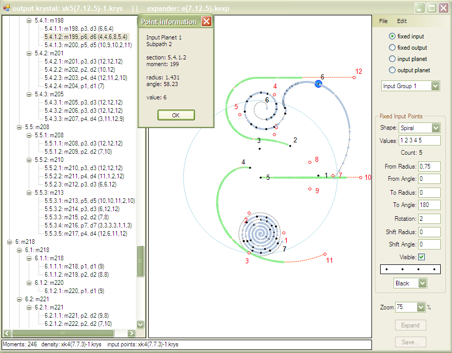
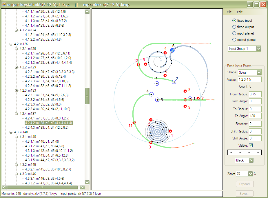
- Expansion field (middle): input points are solid black dots, output points are small red circles. The colours can be changed in the control panel.
-
Control panel (right): at the top of the control panel, there is a set of radio buttons
which set the editor to a state in which it can change the type of points selected:
- fixed input
- fixed output
- input planet
- output planet
After loading a krystal, it is possible to change the input krystals, expander or gametes using commands in the File menu. Gametes are loaded from complete expanders. They are never stored separately.
|
Point groups and planets are added to, or deleted from, the current gamete using the Edit
menu. The bottom four items in this menu duplicate the block of radio-buttons. |
|
|
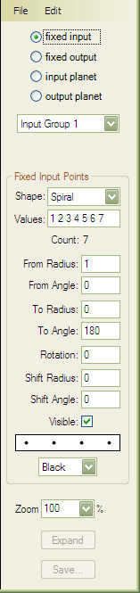
Here is the Control panel from xk3(7.7.1)-1
again: When editing fixed input groups, the top popup menu selects the particular group. Inside the Fixed Input Points area (which changes depending on the setting of the top radio-buttons and the Shape popup),
The controls for Fixed Output Points are exactly the same (with different settings of course), except that the field containing the points preview contains four small circles. The Zoom popup sets the size of the expansion field in the display. The Expand button becomes available when an expanded krystal’s inputs have changed. The strands in the output krystal display in the left panel are also deleted at this time. The Save button becomes available when a krystal is expanded. |
|
|
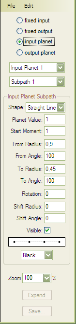
Here is the control panel as it looks while editing a straight line. (This is subpath 1 of planet 1 in xk3(1.7.2)-1.krys.) |
|
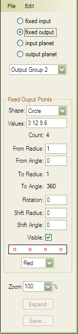
And here is the control panel as it looks while editing a circular group. (This is fixed output group 2 in xk3(1.12.1)-1.krys containing the four output foci 3, 12, 9 and 6.) |
|
-1-Loaded.png)